If you’re in the market for medium-voltage (MV) instrument current transformers (CTs)—whether you’re a utility engineer, industrial plant manager, or electrical system designer—accuracy isn’t just a nice-to-have; it’s non-negotiable. As someone who’s supplied MV CTs for 12 years, I’ve seen first-hand what happens when a CT’s accuracy slips: skewed power metering, incorrect overload protection, even unplanned downtime for critical infrastructure. Last quarter, a manufacturing client came to us after replacing a cheap off-the-shelf CT that had been underreporting current by 8%—costing them over $15,000 in misbilled utility charges in six months. That’s why verifying your MV CT’s accuracy isn’t a one-time test during installation; it’s a routine process every stakeholder should understand. Mv Instrument Current Transformer
First, let’s level-set: MV CTs transform high line current (typically 100A to 10,000A in 5kV to 35kV systems) down to a standardized, safe secondary current (most commonly 5A for industrial use, 1A for precision applications) that meters, relays, and monitoring equipment can read. The accuracy of this transformation is defined by two key specs: ratio error (difference between actual and measured secondary current) and phase angle displacement (timing shift between primary and secondary current), both measured as percentages or minutes. For metering-grade MV CTs—the type we supply for billing and precision load monitoring—accuracy must be within 0.1% for ratio error and 5 minutes of arc for phase angle. Protection-grade CTs have looser specs, but even they need consistent accuracy to avoid false trips or missed fault responses.
So how do you verify that a CT meets its rated accuracy? I’ve broken this down into a step-by-step, field-friendly process that works for both new installations and in-service units, drawing on tests we run in our own calibration lab before every shipment.
Step 1: Prep for Testing Safely (Non-Negotiable for MV Systems)
Before touching any wires, lockout/tagout (LOTO) the MV system. Even small voltages in 15kV systems can cause serious injury, so this isn’t a step to skip. For most field tests, you’ll need three core tools: a portable current transformer test set (sometimes called a CT analyzer), a high-accuracy current shunt, and a digital multimeter (DMM) with a 0.01% accuracy rating. We keep a calibrated test set on our service trucks for on-site client tests, and we recommend calibrating all test tools within the last 12 months—uncalibrated gear will give you unreliable results.
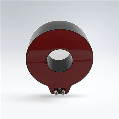
For field tests, you’ll also need access to the CT’s primary leads (the high-voltage wires running through the CT’s core) and secondary wiring (the low-voltage wires connecting the CT to the meter or relay). If it’s a busbar-type CT (the most common for MV switchgear), ensure the busbar is properly sized for the test current—most CT test sets can inject up to 1,000A onto a small busbar, but larger systems may need a temporary test tap installed by a licensed electrician.
Step 2: Choose the Right Test Method for Your CT Type
There are two primary methods to verify MV CT accuracy, and picking the right one depends on whether you’re testing a new unit before commissioning or an in-service unit already installed in the field.
Method 1: Comparison Test (Gold Standard for Field Verification)
This is the test we use 90% of the time when clients ask to confirm a new CT is accurate. The comparison test works by injecting a known, precise current into the CT’s primary side, then measuring the resulting secondary current with a reference standard (our portable reference CT, which is traceable to NIST standards, or a calibrated shunt). The difference between the measured secondary current and the expected secondary current (based on the CT’s ratio) gives you the ratio error, while the test set also measures phase angle displacement.
Let’s use an example: Suppose you have a 200:5 MV CT, meaning its rated ratio is 200A primary current = 5A secondary current. If you inject 200A of primary current into the test set, the CT’s secondary should output exactly 5A. If it outputs 4.994A, that’s a ratio error of (200/5 – 200/4.994) / (200/5) * 100 = 0.12%, which is just at the limit for metering-grade accuracy. If it outputs 4.98A, that’s 0.4% error—way out of spec.
We like this method because it’s fast, doesn’t require disconnecting the CT from its load (for short tests, as long as LOTO is properly applied), and works for all CT types: window-type, busbar, and wound primary CTs. For wound primary CTs (where you wrap the primary wire around the core multiple times), just adjust the test current by the number of wraps: if you have 2 wraps, inject 100A to get the equivalent of 200A primary.
Method 2: Excitation Current Test (For Detecting Core Defects)
While not a direct measure of accuracy, the excitation current test is critical for ruling out hidden defects that can cause accuracy drift over time. Excitation current is the small amount of current that flows through the CT’s secondary winding when the primary is open—used to magnetize the core. A healthy metering-grade MV CT will have an excitation current of less than 0.5% of the rated secondary current at rated primary voltage. If excitation current is too high, it means the core has defects from manufacturing damage, improper installation, or age, which will cause ratio and phase angle errors once the CT is under load.
We run this test for every CT before shipment, and we always recommend running it for in-service units that show accuracy issues. For example, a client recently had a 5-year-old MV CT that was showing 2% ratio error; the excitation test revealed a cracked core from a loose mounting bolt, which was easily repaired once we identified the issue.
Step 3: Test at Multiple Load Points, Not Just Rated Current
A mistake I see even seasoned electrical engineers make is testing accuracy only at the CT’s rated primary current. MV CT accuracy isn’t linear: error increases at low loads (less than 10% of rated current) and at overloads (more than 120% of rated current), where the core can saturate. For metering applications, you need accuracy across the entire load range the CT will see, because utility meters bill based on average current over time, not just peak current.
For example, if your 200:5 CT typically sees loads between 50A and 250A, test at 50A (25% load), 200A (100% load), and 240A (120% overload). If it passes at 100% load but has 1.5% error at 50A, that’s a problem because your metering will be off during low-load periods, when energy costs are still being billed. Our team always specifies that our metering-grade MV CTs have error less than 0.2% across 10% to 120% of rated current, which is a standard we hold to for all shipments.
Step 4: Document Results and Address Discrepancies
Once you run all tests, compare your results to the CT’s nameplate specs. If you’re testing a new CT from a reputable supplier (like us), all units come with a calibration certificate traceable to national standards, so your test results should match that within a 95% confidence interval. If they don’t, don’t panic: first check your test setup—loose wiring, uncalibrated tools, or a wrong ratio input are the most common causes of false errors. We’ve had a handful of clients mislabeled the CT’s ratio during testing, leading to incorrect results, so double-check every input before declaring a CT inaccurate.
If discrepancies are real, here’s how to act: For new CTs, contact your supplier—reputable suppliers will either replace the unit or assist with on-site calibration (we send our service teams to fix CTs within 500 miles for free if the unit was mis-calibrated during testing). For in-service units, if error is under 1% for metering, it might be acceptable if your utility allows a small tolerance, but errors over 1% almost always mean the CT needs replacement or reconditioning. If you need help interpreting results, don’t hesitate to reach out to a supplier with calibration expertise.
Common Pitfalls to Avoid
Over the years, we’ve seen too many teams make these mistakes when verifying MV CT accuracy:
- Skipping LOTO: MV systems carry enough voltage to kill, so never skip lockout/tagout. We trained all our service technicians to complete LOTO steps before even picking up a test tool, and we recommend all clients do the same.
- Forgetting to account for burden: The secondary burden (the load on the CT’s winding, from meters, relays, and wiring) affects accuracy. Your test set should match the actual burden the CT will see in service; if you test at a 25VA burden but the CT will see 15VA in use, the error will be higher in real life. We always include burden specs in our product data sheets, so clients can match test conditions to actual use.
- Ignoring environmental factors: Extreme temperatures (above 40°C or below -20°C) can cause small accuracy shifts. If you’re testing in a hot industrial plant, run a second test after the CT has cooled to room temperature to confirm results.
MV Instrument Voltage Transformer At the end of the day, verifying MV instrument current transformer accuracy isn’t just a technical task—it’s a way to protect your bottom line, equipment, and safety. A 0.5% error might seem small, but it adds up to thousands of dollars in billing errors or protection failures over time. If you’re installing new MV CTs, auditing existing ones, or need help with on-site calibration, we’re here to guide you. Every unit we ship comes with a full calibration report, and our service team can walk you through step-by-step testing over the phone or even send a technician to your site for hands-on verification. Reach out to our team to discuss your current transformer accuracy needs and find the right solution for your system.
References
- International Electrotechnical Commission. IEC 60044-1: Instrument Transformers – Part 1: Current Transformers. International Electrotechnical Commission, 2018.
- IEEE Standard C57.13-2021: Requirements for Instrument Transformers. Institute of Electrical and Electronics Engineers, 2021.
- National Institute of Standards and Technology. Calibration Requirements for Current Transformers Used in Energy Measurement Systems. NIST Special Publication 250-87, 2020.
- Miller, T. J. E. Reactive Power Control in Electrical Systems. Wiley-IEEE Press, 2017.
Dalian Xin’anyue Electric Power Equipment Co., Ltd.
Dalian Xin’anyue Electric Power Equipment Co., Ltd. is one of the most reliable mv instrument current transformer manufacturers and suppliers in China, featured by quality products and good price. Please rest assured to wholesale durable mv instrument current transformer in stock here from our factory. We also accept customized orders.
Address: No.99, Group 1, Chongwangmiao Community, Taiping Street, Pulandian District, Dalian City, Liaoning Province, China
E-mail: sales@dlxay.com
WebSite: https://www.xayelectric.com/
